
Know Your Machine
Whether you are a first-time operator or a seasoned fabrication professional, understanding the various components that make up a press brake and how they work is critical to your success in bending metal. In this overview, we will take a general look at the makeup of a standard hydraulic CNC press brake, but to be effective you must carefully study the manual of the actual machine that you will be running or maintaining.
A Press Brake Walk Around
While most of the action takes place at the front of a press brake, we will start our virtual tour at the side:
- Frame. The frame holds the machine together, with vertical plates called housings on either side of the press brake. These are connected to the bed and a top crossbeam at the front to provide stability for the entire machine. The housings are usually of a C-frame design, with a rounded cavity called the throat facing the front of the machine where the tooling is found. This notched area allows the tooling—and the piece being bent—to extend past the sides of the machine for wider jobs, provided the flange on the part being bent can fit within the throat. Various controls and monitors may also be mounted on side housings. Key measurements to understand are “throat depth” (to determine the size of the allowable flange on full-width jobs) and “between-the-housings” (to determine how wide a job can be that needs an extra deep flange that must be bent within the frame).
- Electrical Cabinet. A metal box called an electrical cabinet will be found on a press brake, usually mounted to one of the side housings. It is where power is hooked up to the machine, and where switches, wiring, and other instruments can be found that need to be accessed. A rack is often found inside the door of an electrical cabinet where the machine manual, schematics, parts lists, and other documentation can be securely stored.
Moving to the front of the machine, we see most of the equipment that will have direct interaction with the workpiece:
- Bed. The flat surface on which the material rests during bending is called the bed. This lower section of the press brake holds the die rail in place and is stationary, except in the rare case of an up-acting press brake where the bed is the moving part. Also known as a lower beam, a worktable, or a workbench, a bed may be designed to extend down past the floor into a “pit” or slit cut into the concrete to give the press brake greater stability.
- Ram. The moving upper part of the press brake that applies force to the material for bending is called the ram. Also known as an upper beam, the ram is where the tooling is attached. Certain monitoring and control mechanisms may be attached to the ram, such as linear scales on either side of the ram for precise positioning, or a limit switch (used in lieu of a CNC control or as a safety backup to one). The length of the ram and bed are the size that is used to determine the length of the press brake itself, as that is the maximum width of material that can be bent.
- Hydraulic Cylinders. Hydraulic CNC press brakes will feature dual hydraulic cylinders mounted at the top of the housings where they are connected on either side of the ram. These independently operated cylinders allow very precise movement of the ram via a CNC control. An important press brake measurement is tonnage, or the maximum force that can be applied by the hydraulic cylinders (or other power source) to a workpiece. A press brake’s “size” is determined by its capacity, or its combined tonnage and length, such as when someone refers to an “80-ton by 8′ brake.”
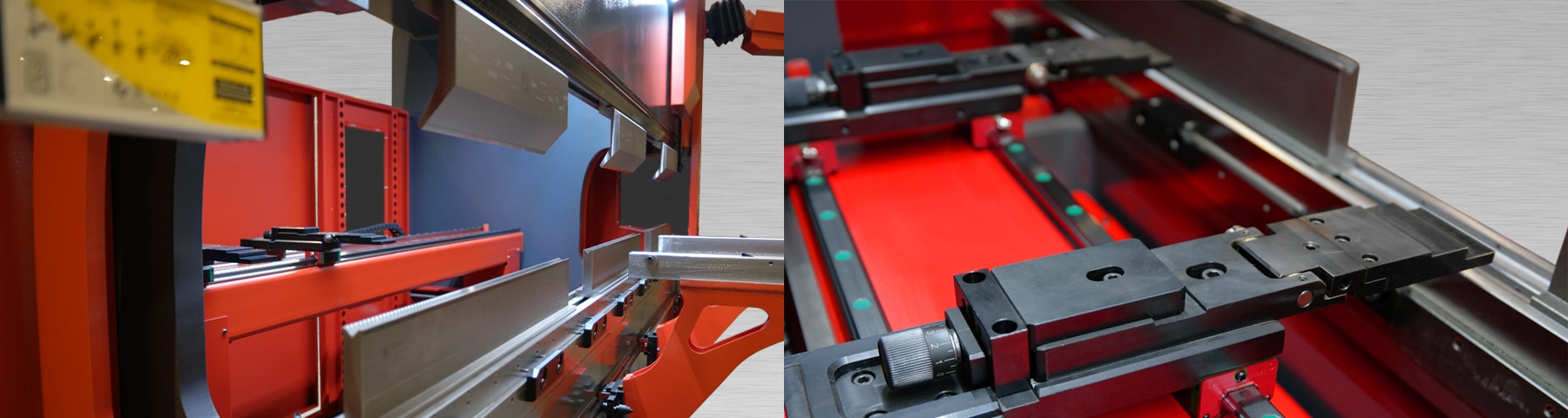
- Tooling. The components that directly interact with the metal to bend it are the exchangeable pieces called tooling. Available in a variety of sizes and configurations to form different angles and types of bends, tooling is generally made from steel and other alloys that are much harder than the material being bent. The top pieces of tooling are called press brake punches and are attached to the ram by a clamping system of some sort. The bottom pieces of tooling are called dies (or V-dies because of their V shape) and are attached to the bed by the means of a die rail. Key measurements to understand are “open height” (also called “daylight”), the distance from the bottom of the upper beam to the top of the lower beam when the press brake is in the fully open position; “closed height,” the distance between those same points when the press brake is in the fully closed position; and “stroke,” the amount of travel from the open to closed positions, determined by subtracting the closed height from the open height.
- Safety Lasers. Mounted on the rams of most modern press brakes are safety lasers, consisting of a transmitter and a receiver. A laser beam runs just beneath the top tooling and triggers the ram to stop and reverse movement if an object such as the operator’s hand breaks the beam.
- Crowning Device. Because deflection (flexing while under a load) occurs in press brake rams and beds while bending, press brakes that are at least eight feet in length will usually feature a crowning device just below the bottom die rail to help compensate for it. Deflection causes the ram and bed to no longer be parallel during the bending operation, so a crowning device will raise the center of the die rail to keep the bending angle consistent across the workpiece.
- Control Panel. An interface for operators to set bending parameters, such as angle and bend length, is called a control panel. These are usually NC (numeric control) or CNC (computer numeric control) panels. Complex CNC controllers are becoming more commonplace, giving the operator precise control over all devices and axes of the machine through programs that can be set up and run. CNC controls are often mounted on an extension arm that is attached to a side housing and swung out around to the front of the machine for easy positioning.
- Pedestal or Foot Pedal. Press brakes of any type will usually feature a free-standing control consisting of foot pedals and/or buttons used to engage the bending operation.
- Sheet Supports. Front support arms that can be positioned at points across the front of the machine or some other type of sheet support is a common feature of press brakes. These devices hold and support the material at the edge of the bed, aiding in accurate bending.
- Covers. The front, sides, and even rear of a press brake may have sections with covers made from painted sheet metal concealing them. These are often for aesthetic purposes—such as covers over hydraulic cylinders—but may also be used to keep operators and bystanders away from moving parts.
Going around to the back of the machine, the final key components come into view:
- Back Gauge. Adjustable material stops that sit behind the tooling on a press brake make up the back gauge. A CNC press brake will feature a powered, automated back gauge that is programmed and operated by the control panel and adjusts the position of the workpiece throughout the bending process.
- Hydraulic System. Visible at the very top of the machine, attached to the top crossbeam, is the press brake’s hydraulic system. These pieces of equipment—which include motors, oil pumps, filters, and other components—power the hydraulic cylinders, providing the force required for bending operations.
Beyond the major components of a press brake are the hundreds of small, yet essential parts that allow the machine to perform its functions again and again with precision. The wise operator will go past understanding just what is needed for programming simple bends and study every aspect of the machine they are working with, always asking “Why?” when they encounter a component whose function puzzles them.
Press brakes are complex machines that fill an essential role in modern metal manufacturing, so the thoughtful fabricator can profitably spend a lifetime learning different aspects about their operation and application that will continually give them a competitive edge over rivals in the local marketplace.