
Determining Coordinates
What is an axis? The Latin word axis meant an axle or a pivot, and the English terms axis and axle derive from it. The meaning shifted over time from simply referring to a physical axle around which an object like a wheel could rotate to an imaginary straight line around which a body like the Earth could turn.
As the concept of geometry was developing, it was determined that a straight-line axis that was intersected by a second straight line perpendicular to it could create a graph system in two dimensions. The intersection point of the lines would be designated the origin, and movement in set increments away from that point could be considered a measurement of distance and location on a plane. Adding a third perpendicular line through the same origin point would allow the mapping of location in three dimensions.
Known as the Cartesian coordinate system (named after the French mathematician René Descartes), this classification of X, Y, and Z axes has found application over the years in everything from construction to air travel. In metalworking, the need to denote precise coordinates became essential once machine tools and metal fabrication machines were invented. No longer could a metalsmith simply “eyeball” a workpiece—the motorized movements within the machine needed to be accurate to produce a functional product.
Beyond Three Axes
In the physical world, all spaces can be measured in three dimensions, therefore the location of items can be determined from an origin point in three axes. X, Y, and Z coordinates can also be used to indicate movement along those axes, such as a piece of metal being inserted a specific distance into a press brake. Not all movements are in straight lines, however. X, Y, and Z are axes, after all, so they each form a line around which an object could be rotated.
Taking the three axes of movement and adding to them the rotation possible on each of those axes, one winds up with six different types of movement that a rigid object could make in three-dimensional space. There is X-axis translation (straight movement), X-axis rotation, Y-axis translation, Y-axis rotation, Z-axis translation, and Z-axis rotation. A common place to see operational examples of these “six degrees of movement” or “six degrees of freedom,” as they are often called, is on an aircraft. Not only does it concern itself with the directions of forward and back, up and down, and right and left, but an aircraft will also rotate around those three axes as well, in movements known as roll, pitch, and yaw.
Movements in Metalworking
Six axes are sufficient to describe the movement of a single object in three directions, but machine tools and metal fabrication machines generally have multiple moving parts that make direct or indirect contact with a workpiece. While each still operates in three dimensions, they will likely have different origin points than the main tool or part of the machine. Therefore, their movements will also need descriptions for operators or programmed controls to follow. Each of these movements is usually termed an axis, which is why you might find a 7-axis milling machine or a 10-axis press brake.
Because each type of equipment operates quite differently from the others, the axes of metalworking machines don’t often mean the same thing, even in basic coordinates like X, Y, and Z. In a press brake, X describes the movement of the backgauge towards the front of the machine, while Y indicates the up and down movement of the ram. In milling, the movement of the table towards the front is considered Y, while the vertical movement of the head is called Z. It is critical that operators of different types of metalworking machines understand the axis designations of each.
The Unique Axes of Profile Rolling Machines
Profile rolls, commonly called angle rolls, have distinctive axis terms all their own. Even X and Y are not perpendicular to each other, as they are in most other circumstances. These types of machines were designed to roll straight pieces of metal into curving shapes. Unlike a plate roll, which will curve flat, wide material like steel plates or pieces of sheet metal, profile rolling machines roll profiles, or long, thin pieces of metal. While many of these pieces will look similar when viewed by their long sides, a close-up view of their leading or tailing ends will show distinct shapes or profiles. Pipe and tube, for example will have a round, hollow profile, while a piece of angle iron will appear like an “L” when viewed end-on. In fact, the frequency of fabricators purchasing these machines for the purpose of rolling angle iron has led to them being popularly referred to as simply “angle rolls” in the industry.
Five parts of a standard 3-roll angle roll engage with the material being rolled: a top roll and two bottom rolls (each with interchangeable tooling to accommodate different profiles), and two angled side supports called lateral guides (often “lateral guide rolls” because they each consist of a cylinder that rotates as the workpiece slides past).
In a motorized angle roll, the bottom rolls generally remain at a stationary height while the top roll is manually cranked up and down. The lateral guides on such a machine can only be manually moved out, away from the machine, to match the workpiece’s position. Axes are usually not a consideration on such manually adjusted machines, though each movement could be denoted as an axis.
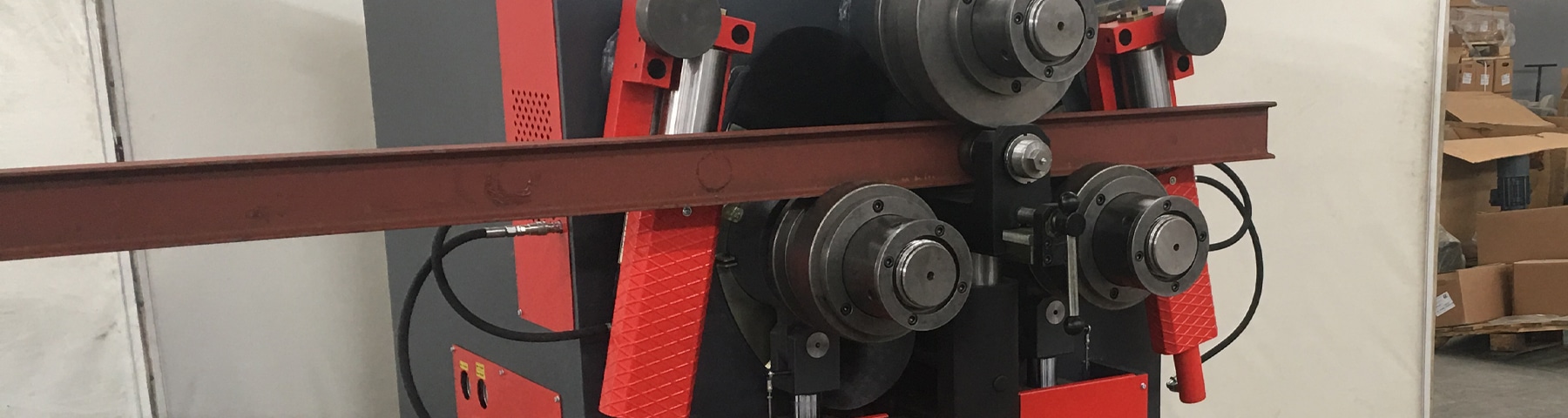
Where the importance of axes comes into play is on more advanced angle rolls, usually ones that are hydraulically driven and operated through a control panel of some type. On a typical 3-roll hydraulic angle roll—and there are 4-roll models in the marketplace as well—the top roll is the stationary one and the bottom rolls move vertically with a slight incline towards the center as they raise so that they can clamp the material to the top roll.
On a hydraulic angle roll, the movement of the material in an arc underneath the top roll is called the R-axis. The movement up and down of the bottom roll on the left side of the machine (from the operator’s position) is the X-axis, while the raising and lowering of the right bottom roll is the Y-axis. Machines with a simple DRO (digital read-out) panel will track the X and Y axes with linear encoders and control their positions through the DRO.
Hydraulic angle rolls will usually have powered lateral guide rolls that are adjustable in three axes each, for a total of six axes. If a hydraulic angle roll is equipped with a PLC, NC, or CNC panel and is advertised as saying that it can control up to eight axes, it is referring to these six, plus X and Y. Each axis of a lateral guide roll is designated with a letter for the axis plus an L or R to indicate the left or right side of the machine from the operator’s perspective. These axes are:
- ZL/ZR. Known as “thrust,” this is the movement of the guide roll out and back from the face of the machine.
- UL/UR. Called “translation,” this is the straight movement of the guide roll away from the origin point of its axis.
- CL/CR. Referred to as “radial,” this is the rotational movement of the guide roll around the origin point of its axis.
The lateral guide rolls control and guide the metal as it is being rolled, allowing the operator to create very precise coils, spirals, and other shapes, as well as rolling profiles in ways that otherwise wouldn’t likely work. One example is rolling angle iron “leg in,” where material is compressed and would normally buckle, but can be carefully done on a machine that has lateral guide rolls with translation capabilities.
Thoroughly understanding the movements of each axis—and how to program them—gives the trained angle roll operator the ability to form accurate curves in profiles, whether they need to roll giant I-beams for structural steel work or simply shape some ornamental ironwork for a custom handrail.