
Which Way Is Up?
The machinist took his son with him to visit his friend’s fabrication shop. After they finished a tour of the facilities, the machinist’s son looked at a pair of images attached to the fabricator’s office wall. The one on the right showed a rocket blasting off straight up, while the one on the left was an identical shot but turned 90° clockwise, so the rocket was flying horizontal. In marker, someone had written “Space X” at the top of the horizontal image and “Space Y” at the top of the vertical one.
The young man pointed out the images to his father, who chuckled over the joke about the rocket builder’s name, but didn’t comment about it, so he decided to speak up himself. “Um, you’ve got the second picture labeled wrong,” he said to the fabricator.
“Oh really?” the fabricator asked, as the machinist just shook his head and smiled. “Why do you say that?”
“Well, it should say ‘Space Z’ over the picture on the right,” the young man replied.
“I bet you work with your father in his machine shop from time to time,” the fabricator speculated. The young man nodded. “Furthermore,” the fabricator continued, “I bet your dad has let you run one of his mills.” Again, the young man agreed.
“If you think back to your math class,” the fabricator said, “when you were graphing in two dimensions, the X-axis was left and right, while the Y-axis was up and down. Once you get into three dimensions, X and Y are usually horizontal, while the Z-axis denotes up and down.”
“That’s right,” the young man agreed.
“That’s how they represent the axes on mills, like the ones your dad has,” the fabricator acknowledged. “Mills have always been machines that work in three dimensions, so X is the movement of the table left and right, Y is the movement of the table in towards the machine or out towards the machinist, and Z is the axis representing the movement of the spindle downward to the workpiece.” The young man nodded his agreement.
Gesturing out at the machines in his shop, the fabricator continued, “Those of us who use press brakes for a living have a slightly different set of coordinates. The earliest press brake operators just thought in terms of two dimensions. Considering the machine from the side, they were concerned how far into the machine the metal was inserted, which they called the X-axis, and about the movement of the ram up and down, which they called the Y-axis. The third axis, dealing with left and right when facing the machine, wasn’t really an issue back then. I’m guessing it was when the sideways adjustable back gauge came into the picture later that the industry first addressed the idea of a Z-axis position for it relative to the operator’s place at the front of the machine. If the workpiece couldn’t be centered in the machine for some reason, those types of back gauges could be slid to a position along the Z-axis to properly support the sheet.”
The young man looked back at the pictures on the wall. “Calling it ‘Space Z’ would still be better in a machine shop, but I now totally get how the ‘Space Y’ joke is perfect in a fab shop,” the young man conceded. “Thanks for explaining to me about press brake axes.” He then quickly added with a note of pride in his voice, “Though as neat as your press brakes are with three axes, you should check out my dad’s new CNC mill. It’s got five axes.”
The young man’s big smile was replaced with a look of surprise when the fabricator himself smiled and responded, “See our big press brake out there? Yeah, it’s got twelve axes.”
Beyond Geometry Class
Anyone who needs to measure volume learns about three basic dimensions—the X-, Y-, and Z-axes. Sometimes a scientist might talk about time being a fourth dimension or even refer to other “higher dimensions” about which we can barely even conceive. When it comes to metalworking machines, however, discussions about multiple axes beyond the basic three are not only commonplace, but they are easily understandable.
When a press brake operator mentions an R-axis, he’s not speculating on another dimension where an alternate planet Earth can be found, like in many a science fiction story. He’s referring to an axis of control in the metal fabrication process. Talking about three axes worked fine in the days before CNC press brakes, but once sophisticated computerized interfaces came on the scene, complete with linear encoders and other sensors, as well as the ability to have precise control over the actions of moving parts like the ram and backgauge components, a nomenclature needed to be developed to describe these additional areas of control.
All axes mentioned in reference to the components of press brakes and other metalworking machines move in different ways within the normal three dimensions of left-right, up-down, and forward-back, but they are controlled independently of all other moving parts of the machine. A CNC press brake operating with 16 axes still sits in the same position of three dimensions on the shop floor it was in before it was powered up (provided all anchor bolts are securely attached to the floor!). The difference between it and a fewer axis brake is that it has much more accurate control of all movements during the bending cycle, producing a finished product of much greater precision.
The following are the common (as well as some not-so-common) axes that can be found on today’s CNC press brakes:
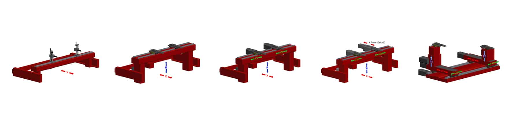
- Y-axis. Y specifies the vertical movement of the ram, the pressure of which bends the metal workpiece. Most CNC press brakes will feature an independently controlled cylinder on each side of the ram and will therefore have two Y-axes, denoted Y1 and Y2. The ability of the CNC to monitor and control the exact positions of each side of the ram provides greater precision and repeatability.
- X-axis. X designates the horizontal movement of the backgauge to position the metal at the correct depth within the machine to allow it to be bent at the proper spot. Since the far side of the workpiece might not be even, many press brakes will have two independently adjustable backgauge fingers to better secure it. If each finger can extend to a different depth than the other—or if each side of the entire backgauge can move independently—then the brake is deemed to have two X-axes, namely X1 and X2.
- Z-axis. Z is the horizontal movement left and right of the backgauge fingers. If the fingers aren’t connected and can move to different positions from each other, those positions are called Z1 and Z2.
- R-axis. To accommodate flanges and other factors, many press brakes will be equipped with a backgauge that can be raised or lowered. This vertical movement is considered the R-axis. If each backgauge finger can independently move vertically, then they are designated R1 and R2. When fabricators speak of a six-axis backgauge, they are referring to one that features CNC control of two fingers in three axes each, specifically R1/R2, Z1/Z2, and X1/X2.
- Delta X. For the fabricator who needs to position a sheet at an angle in their press brake but can’t afford to upgrade to a six-axis backgauge, an option called Delta X can be used. Also known as X Prime, this extra axis is created by replacing or adding onto an existing backgauge finger equipment that allows it to move forward or backwards a few inches in the x-axis.
- CNC Crowning. While crowning—a function for compensating for the deflection that naturally occurs in press brake bending—might not be thought of as an axis in the traditional sense, it does qualify if it can be controlled by the CNC panel on a press brake. Deflection is the distortion of the ram and bed that takes place when it is put under a load in a bending operation, and the deformation increases the further one goes towards the center of the bed, away from the hydraulic cylinders on either side. A crowning device will raise the center of the die rail so that the bending force is applied equally across a long workpiece, resulting in a uniform bend angle.
- Die Shifting. Some press brakes are equipped with the ability to shift a die forward and back a few inches along the X-axis. This is useful for moving a multi-opening die block automatically to the correct opening for the given operation.
- Sheet Handling Equipment. Any component that can be added to a CNC press brake and can be controlled as part of a bending program can technically be called an axis, especially if it handles the material itself. If a brake has been optionally equipped with CNC-controlled equipment like a sheet follower (a device that supports a large workpiece in front of a brake as it moves upward while being bent), a front feeding system, an unloading system, or any robotic interface, then each of those is considered an axis.
Find the Axes that Fit Your Needs
The more axes that a CNC press brake has control over, the more precise and complex each bending operation can be. Depending on the type of metal fabrication work that your shop does, you should acquire a press brake with enough axes built in (or optionally added) so that you can meet your customers’ every exacting requirement.
Find a reliable metal fabrication equipment dealer that carries top-of-the-line machines and ask them to go into detail about all the pros and cons of adding each available axis to the machine you are considering purchasing. Look carefully at your past, present, and projected future jobs and weigh the benefits of the extra axes against the increased cost of each.
If you wind up buying more axes than you consistently require, simply expand your reach out to find new customers who need what you can offer. If you really don’t do enough large jobs to justify your new sheet followers, approach companies who need large pieces bent on a regular basis. If the Delta X that you added to your machine isn’t used very frequently for positioning sheets at an angle, try to find smaller jobs to perform where it can serve as a side gauge to help support a tiny workpiece.
Just remember that the greater number of axes your press brake has, the greater versatility your shop possesses, and that always opens the door to newer and more profitable possibilities.