Increasing Your Vocabulary
If you are looking to get into metal fabrication in general and bending on a press brake specifically, there are some terms you need to become acquainted with before you begin. While the basic concepts of this technology can be grasped fairly easily, without knowing the common industry language one can quickly become a little lost.
Even veteran metalsmiths can use terms and have a gist of their basic meanings without knowing exactly why things are called what they are. Take the very term “press brake” for example. It’s easy to explain the “press” part—like a classic shop press, a tremendous pressure moves one section of the machine towards another with a workpiece in-between to be fabricated in some way by the two sections. The “brake” part gets a little trickier, however, especially for those new in the industry: some have speculated that the bonds of metal are “breaking” in the bending process, so the word must come from that, even with the different spelling; others have assumed that the ram comes to a stop or “brakes” at the bottom of the bend, so that must be where the term originates. Both are clever. Both are wrong.
The archaic meaning of the term “brake” as used here—which actually comes from the same Old English roots as the two similar words above—means to deflect something and change its direction. In this case it has to do with putting a fold or bend in a flat piece of metal, literally changing its physical direction.
Now, knowing the origin of words isn’t all that helpful—unless you need to keep the conversation going at a boring social gathering—but knowing what the words themselves are and mean will make the learning curve a little less steep when becoming familiar with the fabrication concepts themselves.
Here are a few of the basic terms, not in an A-to-Z list, but rather grouped by subject for easier association. Fabricators are encouraged to keep a notebook or digital file where they compile unfamiliar industry words and ideas as they come across them for future reference.
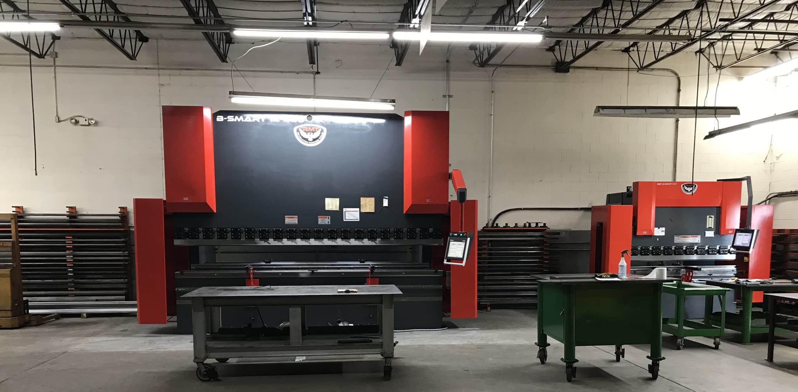
Parts of a Press Brake

The foundational component of the press brake is the frame, consisting of two side housings (usually of a C-frame design) connected together by a bed or worktable at the bottom, with a moving ram or upper beam at the top that brings the tooling together to make the bend. A punch holder with clamps or a clamping mechanism is attached to—or is part of—the upper beam to secure the punch tooling in place, while a die rail for holding dies is mounted on the bed.

A few brakes have an up-acting operation where a lower beam moves a die upward into a punch on a fixed upper frame. Some heavier-duty press brakes will have a taller bed that extends down into a pit (a slit cut into the concrete floor) for greater stability while in operation. Decorative covers for various parts of the brake may be made out of painted sheet metal, but they are for aesthetic purposes and don’t contribute to the structural integrity of the machine.
A back gauge is a device that sits behind the ram and the bed, relative to the operator. It is used to accurately position the workpiece so that the bend is made at the desired spot. Programmable back gauges can automatically move between bends to reposition the workpiece for making more complex parts with greater accuracy and efficiency. The press brake will also include the mechanism for moving the ram. In the case of a hydraulic press brake, this would usually consist of two hydraulic cylinders, each mounted to a different side of the ram, with a hydraulic unit located nearby (such as on top of the brake) to power them.

The brake will be operated by a control unit of some sort, such as a control panel. Many modern press brakes will be operated from a CNC (Computer Numerical Control) panel, which allows very minute control of the movements of the different parts of the brake in multiple directions at the same time for extreme precision. The accuracy of a brake is measured by repeatability, or the machine’s ability to move to exactly the same position repeatedly in order to make identical parts time after time. A moveable foot pedal is generally also used, in order for the operator to activate the bend that has been set up while he is close-up and holding the workpiece in place. Various sensors and stops keep track of where the ram and other press brake components are throughout the operation.
Press brakes can also include things like sheet support arms (extensions that are mounted to the front of the machine for supporting—and sometimes gauging—the workpiece as it is being bent), a gibb adjustment (a motion control device for fine tuning the movement of the ram) and a safety laser (a safety device that can immediately stop the brake if an operator’s hand or other object interrupts the beam near the area of the bend).
Press brakes are categorized by their capacity, which is measured in tonnage, or the maximum pressure or force that can be applied by the machine to a workpiece. When press brake manufacturers refer to the length of a machine, they usually aren’t talking about the overall size of the brake itself, but rather the working length of the ram and bed—another critical measurement of a press brake’s capacity to bend.
“Distance between housings” refers to the size of the gap between the side housings of the frame. This is an important measurement to be aware of because a really deep workpiece will bend up inside of the machine frame and not just within the smaller space of the throat, the cutaway part of the side housings that allow the ram and bed to extend out sideways beyond the width of the frame. Throat depth is how far the cutout extends into the frame, which in turn limits the maximum size of the bent part of the workpiece—known as the flange—if bending to the full length of the machine. Narrower parts that fit between the housings can be bent with longer flanges.
Other important press brake measurements include stroke length, which is the distance the ram can travel downward, and open height—often called “daylight”—the distance between the bottom of the ram and the top of the bed when the ram is raised to the top of the stroke and no tooling is present.
ABCs of Bending
There are three basic types of press brake bending: air bending, bottom bending and coining. Each involves a different process to change the shape of the workpiece being bent.
- Air Bending | A very common process used by fabricators to bend metal on a press brake, air bending makes relatively little contact with the metal compared to the other two types. Only certain points of the sides of both punch and die touch the metal, with the bend angle being determined by how deep the punch descends into the die, not the actual shape of the tooling pieces themselves.
- Bottom Bending | Also known as “bottoming,” bottom bending brings the punch and die closer together than air bending so that much more of the tooling is contacting the metal, allowing the bend to better conform to the shape of the punch and die. More tonnage is required with bottom bending than air bending.
- Coining | As the name implies, coining comes from the metal fabrication process used to make coins, using extremely high tonnage to compress and conform the metal to nearly the exact angle of the tooling.
Related terms include bend angle, the angle between the flange and the rest of the part once it is bent, and springback, which refers to the tension in the material of the workpiece that will relax the shape back a little after the pressure is relieved. Because of the amount of springback that is expected in air bending, operators usually bend a couple of degrees more acutely to allow the workpiece to settle back to the correct angle. Springback is also present with bottom bending, but is nearly eliminated in coining, since the molecular structure of the workpiece is actually changed under the extreme pressure.

Back to Geometry Class
Most high school students take geometry just to fill a math requirement without figuring on using it very frequently later on. Those students who wind up in metal fabrication quickly discover that learning how to determine the relative position of things in three dimensions (or axes) can actually come in very handy. In press brake bending and other metalworking, it’s essential for a fabricator to be aware of not only the simple X, Y and Z axes, but also some other geometric relationships.
- X-Axis | The front to back dimension of the press brake is the X-axis. The operator controls the forward to back movement of the back gauge, which determines the length of the flange. Independent back gauge movement is measured as an X1 axis (left) and an X2 axis (right) when facing the machine from the point of view of the operator at the front. Controlling the separate movement of dual axes like these is used to create an angled bend line in a workpiece.
- Y-Axis | The vertical movement of the ram is called the Y-axis. CNC press brakes allow independent control of each side of the ram if the brake is equipped with two separate cylinders. The left side of the ram is called Y1, while the right is Y2. A CNC brake with independent cylinders is often referred to as a “Y1/Y2 machine.”
- Z-Axis | The left to right dimension of the press brake is the Z-axis. This is used to measure the positions and motion of the back gauges, designated Z1 (left) and Z2 (right).
- R-Axis | The vertical movement of the back gauge is considered the R-axis and is available to control on some CNC press brakes. R1 and R2 refer to the up and down movement of the left and right back gauges, respectively
Related terms include deflection, the temporary deformation in the Y-axis of the bed and the ram towards the center when under pressure, and deflection compensation, methods of counterbalancing the effects of deflection. This is usually accomplished by either inserting shims under the lower die or by using a crowning device to slightly raise the center of the machine under the die. Crowning helps to equalize the force across the tooling so that the deformation caused by deflection isn’t passed into the finished workpiece.
A World of Knowledge
We’ve just scratched the surface of the terminology used with press brake fabrication. To be an effective press brake operator, one also has to learn—and be able to work with—such concepts as bend allowance, bend deduction, elasticity, elongation, inside bend radius, K-Factor, neutral axis, outside setback, tensile strength and yield (most of which also require some math skills).
While it may seem intimidating at first, the world of metal fabrication and press brake operation is fascinating and can lead to many opportunities for both profit and creativity for those who take the time to learn and master its concepts and skills.