What Is a Press Brake?
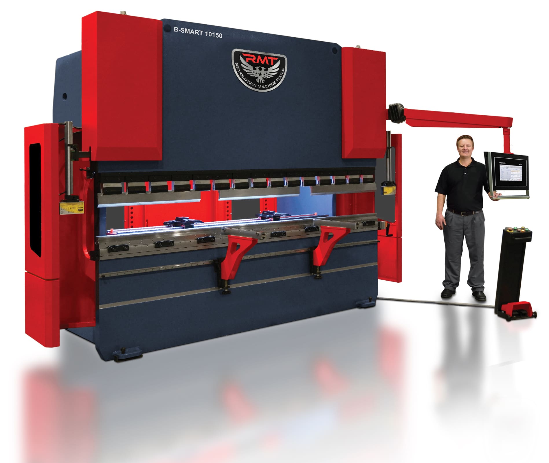
Press brakes are powered machines commonly found in the metal fabrication industry that are used to bend sheet metal or plate metal into angles. The bends are made by placing the metal between matching convex punches and concave dies that are at least as wide as the material, then applying intense pressure to bring the punch and die together, folding the metal between them.
Shape Up!
Methods for shaping sheet metal have been around as long as the material itself. Thousands of years ago humans discovered that pounding metals like copper and lead could flatten them out for use as armor or building materials. Then the sheets of metal could be further shaped by hand tools, often employing a form or mold to bend or curve it. With the invention of the anvil and later the vise, hand-forming right-angle bends in sheet metal became a more precise art.
Give Me a… Brake?
Once rolling machines were developed to improve the process of flattening metal into sheets, machines to fold these sheets into different angles were developed along with them. The bar fold, invented in the 1820s, provided a simple way to clamp and bend metal, while the development of the cornice brake in the 1880s allowed for longer and wider pieces of metal to be bent because of its design.
While it sounds like the word “break” and is spelled the same as a brake on a car, the meaning of brake in this case is different (though all three terms come from the same Old English roots). This archaic meaning of the word implies deflecting or changing the direction of something and in modern usage refers to bending, folding or flanging flat pieces of metal.
A De-Pressing Concept
With the advent of flywheel-driven press machines to make the compression of metals and other materials easier, it was not many years before someone decided that there could be an application of this technology to bending metal as well. Instead of folding metal between a swinging leaf and a stationary one, this new style of brake would generate tremendous force to move a ram with a punch against a stationary ram with a die to bend a sheet of metal between them.
As the means of applying force in presses and similar machines became more sophisticated throughout the 20th century, press brakes followed suit, moving from flywheel machines to pneumatic and hydromechanical ones and finally to the hydraulic press brakes that are still the most common type today. Hybrid electric servo-driven hydraulic press bakes and fully electric brakes would follow in the dawn of the 21st century.
What’s in a Name?
In the move from manual to powered brakes, a change was eventually made in how press brake machine capacities were indicated. Instead of calling a brake a “10′ x 16-gauge” model (describing the maximum length and thickness of material that can be bent), most press brakes are now referred to by length and “tonnage.”
Tonnage is the amount of pressure a press brake can generate, but that translates to the ability to bend different thicknesses of metal, depending on the length and type of material and the size of the opening in the V-die that is being used (the wider the opening, the lower the tonnage required). So, a 250-ton x 10′ press brake can exert a maximum pressure of 250-tons and has a bed wide enough for a 10′ long work piece, but determining what thickness of material at what length can be bent on it (and using what die) requires a mathematical calculation — or at least a glance at the press brake tonnage bending chart that will likely come with the machine.
Beyond the 3rd Dimension
In geometry class, students are taught about representing the three dimensions using the letters X, Y and Z. Press brakes use a similar system, but go beyond three axes these days in order to control very precise bending in metal. The development of the back gauge allowed an x-axis to be set for how far the sheet would go into the brake, determining where the bend would be made. The up and down movement of the ram was considered a y-axis, allowing different angles to be bent depending on how far down into the die the metal was pushed. The z-axis was simply the horizontal position of the back gauge behind the metal.
With the onset of computer numeric control (CNC) technology, each side of the ram could be equipped with its own independently controlled hydraulic cylinder, creating a Y1 axis and a Y2 axis. The height of the back gauge was considered a new axis, called R. Two independently moving back gauges could have two different heights (R1 and R2), two different horizontal positions (Z1 and Z2) and even two different distances from the ram (X1 and X2). Other adjustments, such as crowning (slightly raising the center of the beam to compensate for bowing) give today’s CNC press brakes very precise control over how they bend metal.