
Pipe spool systems are critical components in modern industrial piping networks, serving as the prefabricated sections of piping that connect various process equipment and structures. These systems are used extensively in industries such as oil and gas, petrochemical, power generation, water treatment, and shipbuilding.
The fabrication of pipe spools is a precise and controlled process that ensures each assembly meets design specifications, dimensional accuracy, and quality standards before being installed at the project site. This article explores the complete fabrication process of pipe spool systems—from design and material preparation to welding, inspection, and final delivery.
Understanding Pipe Spool Systems
A pipe spool refers to a prefabricated assembly consisting of pipe segments, fittings (such as elbows, tees, reducers), flanges, and other components that are welded or bolted together according to the design drawing. Instead of fabricating the entire piping network on-site, fabrication shops create these spools under controlled conditions, improving quality, efficiency, and safety. Once completed, spools are transported to the site for installation, where they are joined using bolted flanges or field welds.
The key benefits of prefabricating spools include:
- Reduced field labor and installation time
- Improved quality control through shop-based fabrication
- Enhanced safety due to fewer on-site welding operations
- Lower overall project cost and schedule optimization
Design and Engineering
The fabrication process begins with detailed engineering and design. Engineers use 3D modeling software such as AutoCAD Plant 3D, SmartPlant, or PDMS to develop isometric drawings and piping layouts. These drawings specify the material grades, dimensions, wall thicknesses, end preparations, weld details, and tolerances.
Each spool drawing typically includes:
- Spool identification numbers
- Pipe lengths and diameters
- Location and orientation of fittings
- Weld joint numbers and type
- Dimensional tolerances and test requirements
A Bill of Materials (BOM) accompanies the drawing, listing all components required for fabrication. The design is reviewed for constructability, weld accessibility, and compliance with applicable codes such as ASME B31.1 (Power Piping) or ASME B31.3 (Process Piping).
Material Procurement and Inspection
Once design approval is complete, the next phase is material procurement. Pipes, fittings, and flanges are sourced according to project specifications. All incoming materials undergo visual and dimensional inspection, material traceability verification, and positive material identification (PMI) tests to confirm compliance with standards such as ASTM or API.
Materials are tagged with unique identification numbers to maintain traceability throughout fabrication. For high-pressure or critical service piping, mill test certificates (MTCs) are reviewed and recorded in the quality documentation.
Cutting and Preparation
After inspection, materials are sent for cutting and end preparation. Pipe cutting can be performed using several methods—manual gas cutting, band saws, plasma cutting, or CNC pipe cutting machines—depending on the pipe size and thickness. CNC machines are often preferred for high precision cutting with minimal distortion.
Following cutting, end preparation (beveling or facing) is done to ensure proper weld joint configuration. Beveling machines or lathe tools are used to create standardized weld bevels according to ASME Section IX requirements.
All cut ends are cleaned, deburred, and checked for roundness. Dimensional accuracy is verified before proceeding to the fit-up stage.
Fit-Up and Assembly
The fit-up process involves aligning and assembling the individual components according to the spool drawing. Proper alignment is critical to ensure weld integrity and dimensional accuracy. Clamps, jigs, and fixtures are used to maintain correct orientation and spacing between components.
Tack welding is performed to hold the components in position. The assembly is then verified against the design dimensions using measurement tools such as tapes, calipers, and alignment lasers. Any deviations beyond tolerance are corrected before final welding.
Fit-up inspection ensures:
- Correct orientation of fittings and flanges
- Consistent root gap and alignment for welding
- Accurate dimensional conformity
Welding
Welding is one of the most critical steps in pipe spool fabrication. Depending on the project requirements, welding may be performed using GTAW (TIG), SMAW (Stick), GMAW (MIG), or FCAW processes. Welding procedures and qualifications are governed by codes such as ASME Section IX.
Each weld is performed according to an approved Welding Procedure Specification (WPS), which defines parameters like current, voltage, filler material, and preheat/interpass temperature. Welders are qualified under Welder Performance Qualification (WPQ) tests to ensure competence.
Inter-pass cleaning, preheating (for certain materials), and post-weld heat treatment (PWHT) may be required depending on the material grade and service condition.
Inspection and Testing
Quality assurance plays a vital role throughout the fabrication process. After welding, the spool undergoes a series of non-destructive examinations (NDE) to verify weld quality and detect any discontinuities. Common NDE methods include:
- Visual Inspection (VT)
- Radiographic Testing (RT)
- Ultrasonic Testing (UT)
- Magnetic Particle Testing (MT)
- Dye Penetrant Testing (PT)
Dimensional checks are conducted to ensure compliance with isometric drawings and project tolerances. Hydrostatic or pneumatic pressure tests are performed as required by the design code to verify leak tightness and strength.
All inspection results are documented in Inspection Test Reports (ITRs) and compiled in the Manufacturer’s Data Record (MDR) for final approval.
Surface Treatment and Painting
After successful inspection, the spools are prepared for surface treatment and coating. This step protects the system from corrosion and extends service life. The process may include:
- Surface cleaning using shot blasting or sandblasting
- Primer coating with epoxy or zinc-rich materials
- Topcoat painting according to client specifications
Coating thickness is measured using dry film thickness (DFT) gauges to ensure uniform coverage. Painted spools are then tagged with identification labels for traceability.
Final Assembly, Marking, and Dispatch
The final stage involves marking, documentation, and dispatch. Each spool is clearly marked with its spool number, line number, and orientation details for easy identification during installation. Dimensional and weight data are recorded for logistics planning.
Spools are then packed and loaded onto transport vehicles using protective measures such as wooden supports, plastic wrapping, and padding to prevent damage. The final documentation—including inspection reports, material certificates, and as-built drawings—is submitted to the client for review and approval.
Mastering Pipe Spools in Your Shop
The fabrication of pipe spool systems is a meticulously controlled process that integrates engineering precision, skilled workmanship, and stringent quality control. By shifting fabrication from the field to the shop environment, industries achieve higher efficiency, improved safety, and superior product quality.
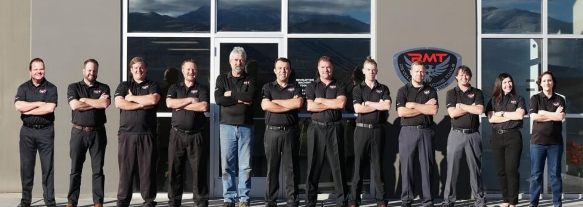
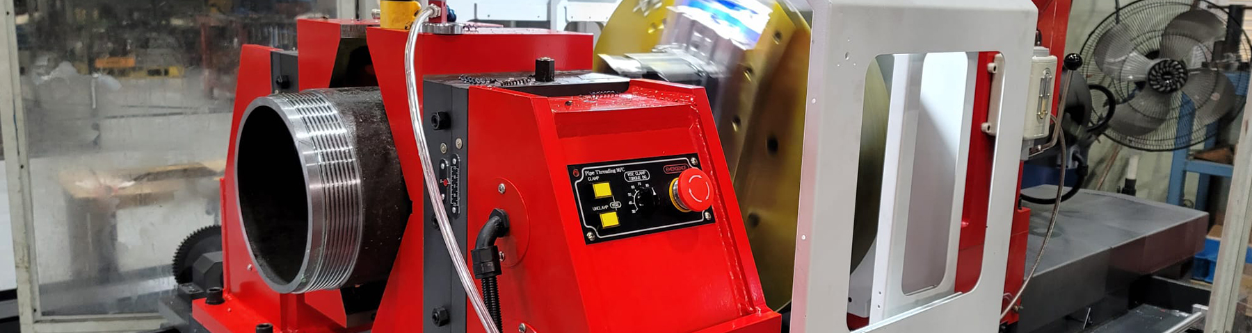
Revolution Machine Tools offers a line of equipment specifically geared towards those who work with pipe spool systems. The RMT Pipe Spool Master Series are a line of highly accurate, heavy-duty machines designed to perform various operations on pipe ends, such as beveling, facing, and threading. Unlike traditional lathes, these machines hold the pipe stationary while the cutting tool spins around it, making the process safer and allowing for the processing of very long pipes.
If you work in the field of pipe spool system fabrication, give the machinery consultants at RMT a call today for a competitive quote on one of these metalworking wonders and improve your bottom line in ways you’ve never considered.