A Sinking Feeling
Your elderly neighbor asks if you can help him hang lights on his house for the upcoming holiday season. “Sure,” you reply, glad to assist the kindly old man who’s always been so friendly to your family.
When you arrive, you see that he’s already set up some makeshift scaffolding along one edge of the house. “You just can’t get a ladder up over the shrubbery here in the middle,” he says, “so running some boards across these two ladders has always worked like a charm.”
Noting your skeptical expression as you look over his contraption, he quickly adds, “I’ve never had a problem going up there myself, but now with this dang vertigo my wife says I shouldn’t try it anymore.” You figure that if it has worked for him, it shouldn’t be a problem to someone as relatively young and healthy as yourself.
You ascend one of the ladders and begin to hang the lights with ease, but as you inch out towards the middle of the boards, you feel them sag more and more under your weight. You recognize that you have quite a few pounds on the skinny old man and question the wisdom of your situation.
As you finally get safely to the other side, you smile as a silly thought comes into the metal fabricator part of your brain: “Boy, I wish I had shimmed under the middle of those boards first.”
Deforming Under a Load
While obviously different than the phenomenon of press brake bending, the situation with the two ladders has one similarity—an object being deflected while under pressure at a point of less support. The term deflection, as it applies to structural engineering, refers to the amount that part of a structure is displaced (or deforms) when it is put under a load.
In the field of physics, Sir Isaac Newton’s classic Third Law of Motion states that for every action there is an equal and opposite reaction. Just as the flap of a bird’s wings pushes air down and back, so the opposite force pushes the bird up and forward. A sheet of metal plate doesn’t seem very sturdy when compared to a large, heavy press brake, but when the press brake pushes against the thin workpiece, the workpiece pushes back.
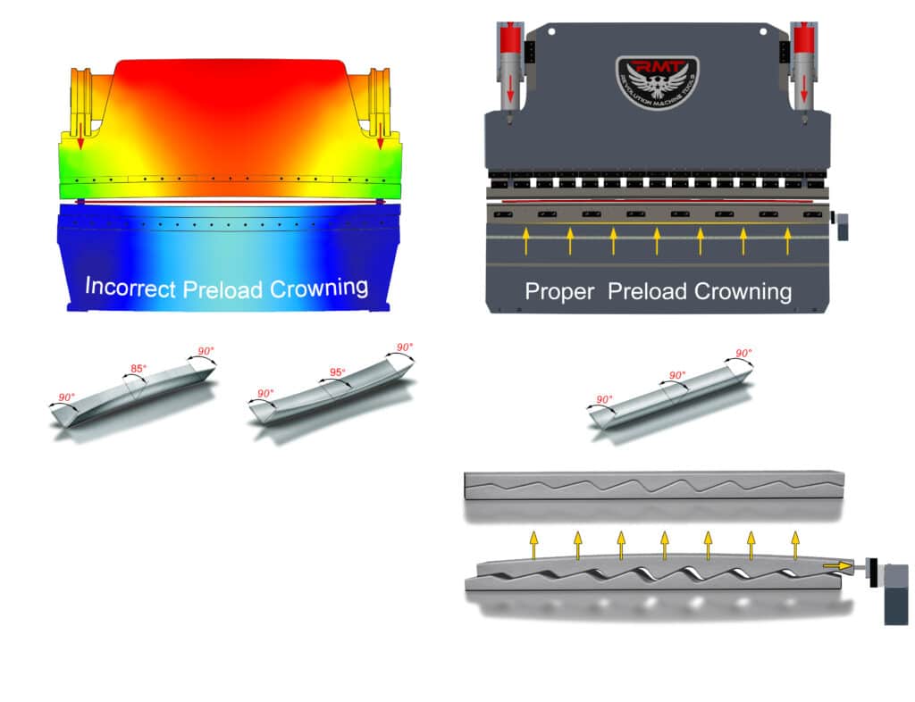
A hydraulic press brake has two hydraulic cylinders, one mounted at each side of the ram near the frame. The force pushing the ram down is at its greatest closest to those cylinders, with a tiny amount of “give” running along the rest of the ram, increasing as the center is approached. Likewise, the bed of the machine is sturdiest where it meets the frames at each side. The ram and bed each flex minutely during a bending cycle, especially towards the center.
As force is applied to the workpiece, its resistance is sent back into the ram and the bed, causing the less-supported center of each to yield ever so slightly. While the distortion in the body of the machine is so small that it can’t be seen by the naked eye, its effects become readily apparent when examining a workpiece that comes off the machine with a bend that changes degrees slightly between the ends and the middle. A part that is bent correctly with a 90° angle at each end might have a wider 92° angle in the middle due to deflection.
Deflection Correction
The introduction of the hydraulic Y1/Y2 press brake brought greater power and control to the craft of metal bending, but it also made deflection a more common issue in metal fab shops. The old mechanical flywheel-driven brakes of decades ago relied on the force of the heavy ram coming down to evenly bend a workpiece. The newer hydraulic machines could be smaller and lighter because much of the bending force was now provided by the cylinders, but that force was concentrated in the edges of the ram adjacent to the cylinders, with the rest of the ram in-between essentially “coming along for the ride.”
To compensate for deflection in the center of the bed, the tried-and-true method of shimming was brought into play by press brake operators. Metalworkers and others have long used multiple thin strips of metal or other material to offset minor issues in their work, such as tightening a component that is too loose or raising one that is slightly too low. By putting thin strips of metal (or even paper) between the center of the bottom die and the ram, a “crown” or rounding was created in the bottom die, raising it higher in the middle than at the sides.
While it seems counterintuitive to curve a previously flat bending surface to create a part that comes out straight, this added thickness was found to be adequate to counteract the flexing found at the center of the bend. Adding shims under the bottom die is still a commonly used method today, with operators honing their skills through trial and error to be able to estimate how much shimming will be needed for a job, then adjusting the number of shims as test parts are run until one comes out perfect.
More efficient—though also more costly—techniques of press brake crowning have been developed over the years. The two common methods are:
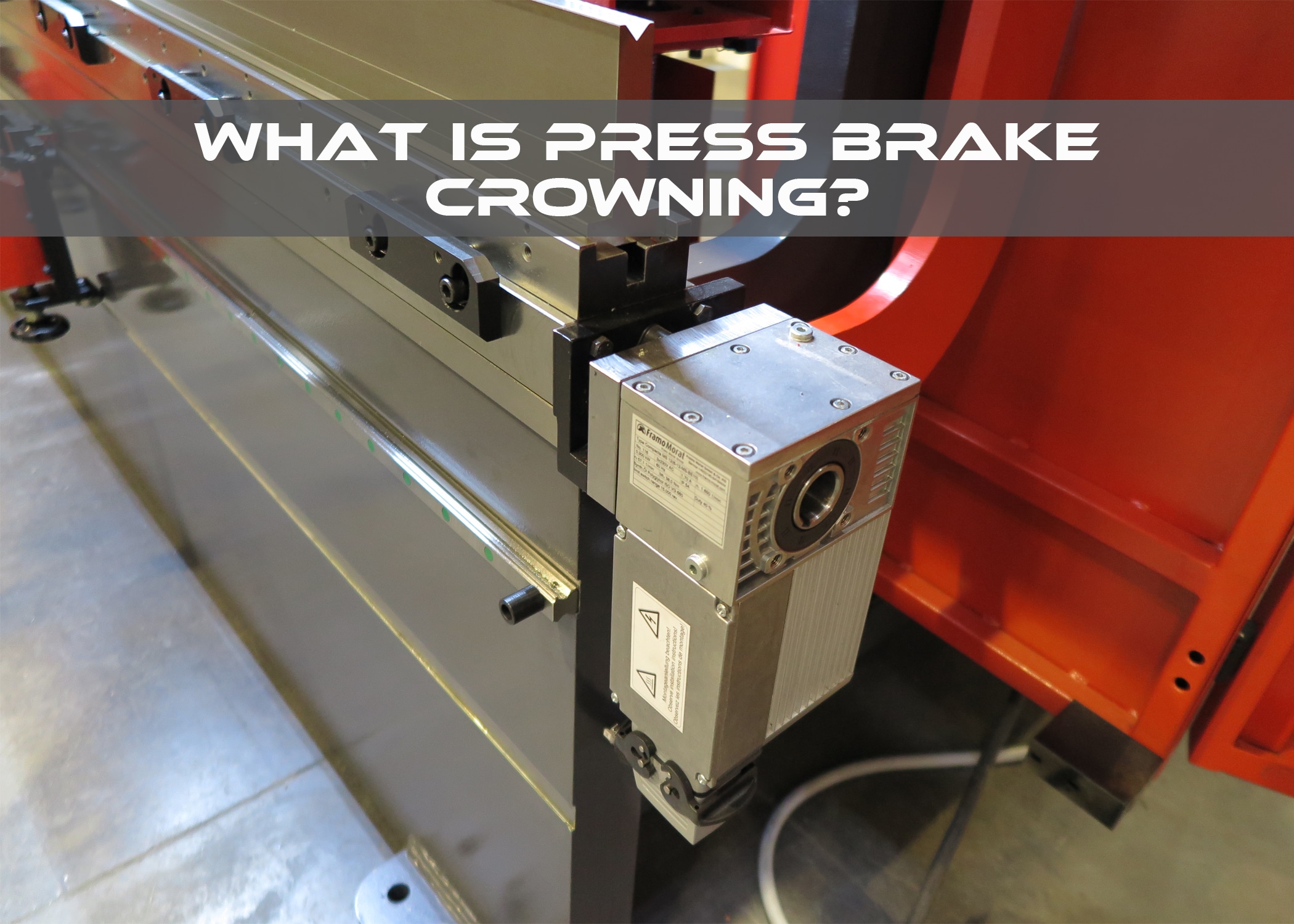
- Mechanical Crowning. Someone came up with the idea that if shimming worked to raise the bottom die, why not just make a die holder that could be manipulated to do the same job? Mechanical crowning systems can be added to virtually any press brake and contain an upper and lower section with facing edges that are cut like a sine wave, with the peaks and valleys increasing in length towards the center of the device. Featuring either a hand crank or a CNC-controlled motorized mechanism at one end, when operated the upper section moves horizontally along the lower, raising as its slopes slide along the ones on its lower counterpart. Because the slopes are steeper towards the center, it gets pushed up farther than the extremities, creating a crown underneath the bottom die.
- Hydraulic Crowning. It was reasoned that since hydraulic cylinders are pushing the sides of the ram downward, couldn’t hydraulic cylinders also be utilized to raise the center of the bed to produce the necessary crowning to compensate for deflection? Many press brake manufactures will mount between one and five CNC-controlled hydraulic cylinders in the beds of some of their machines that push upwards during the bending cycle to crown the bottom die at the same time the tooling engages with the workpiece. Many such systems also feature “dynamic crowning,” a monitoring system that allows the CNC to adjust crowning throughout the operation for greater accuracy.
A Crowning Achievement
The advent of press brake crowning to compensate for deflection and prevent the deformation it causes from being transferred into workpieces has greatly revolutionized the world of metal bending. Crowning is critical in producing precision parts on a press brake by evenly maintaining the bending forces across the tooling and die.
Crowning itself won’t guarantee a perfect bend—a variety of factors come into play, such as operator skill, keeping a press brake properly maintained, and using precision-ground tooling that’s correctly mounted. The metal fabrication shop that combines all these components will find themselves achieving accurate bends time after time.


